Theoretical Considerations
From the 1956 book, Model Power Boats by Norman G. Taylor
Anything that works has more than ordinary appeal to the general public, as witness the crowds at any of the important model power boat contests and regattas, or even the vast number of people (both young and old) who gather so rapidly around a model when it appears at the water's edge! A model powerboat combines the fascination of the miniature; with the allure of the thing that goes-it has life and motion and makes a decided appeal to the eye and ear, especially when it is a scale model.
Practical modelers are sometimes disposed to scoff at the mere word, "theory" and deny its usefulness; others adhere slavishly to the idea that by calculation, formula and algebraic conjuring it is possible to evolve a stupendous success.
Both are wrong, because the theoretician and the practical exponent can learn something from the particular knowledge of the other; therefore, the idea must surely be to combine a reasonable amount of the theory with the results of practical experience in all models designed and built.
The theory-man merely endeavors to coordinate the accumulated experiences of the past, and by an analogy, by accurate deduction and by inference, to look forward into the future. Further than this, theory can and does enable the practical man to obtain his ends or produce a better result with a minimum of labor.
After all, there must be a reason for every happening, and so-called theory aims at giving reasons and stating laws, which govern them. Furthermore, it attempts, with no small degree of success, to enable the naval model architect to design a model boat and fulfill stated conditions.
The student of naval model architecture finds that there are manifold difficulties to overcome in the design of a successful model powerboat. Stability indicates the need for a broad boat and the correct placing of the, "metacenter", the demand for speed necessitates the fine lines, while other requirements such as radio control and steering qualities may well introduce fresh factors. To overcome all difficulties and produce a harmonious design is the aim of all of naval architects.
Primary attention must be given to grasping the fundamental principle of buoyancy, or the power a ship possesses of floating in water, while at the same time maintaining proper trim and stability. At first glance it seems impossible that a model constructed of heavy material should float. That a boat can do so is due to, "displacement" or "buoyancy"--that is to say, when a boat is floating in the water it displaces or pushes away a volume of water equal in weight to the total weight of the model.
For example, if a bowl of water, full to the brim, contains 6 pounds weight of water, and into this a rectangular block of wood weighing exactly 1 pound is introduced, it is obvious that a certain quantity of water will overflow. If the wood is removed and the amount of water remaining in the bowl is again weighed it will be found that it and now weighs exactly 5 pounds, thus showing that 1-pound weight of water has been displaced.
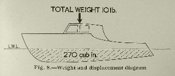
The first thing when designing a model powerboat is to insure that the volume of that part of the vessel to be immersed in the water shall displace a weight of water exactly equal to the total weight of the boat. This principle is the most vital, (of the many involved) when designing a model boat. For a boat to be able to float, it's immersed volume, (example, the part of the hull that sinks into the water, must displace a volume of water equal in weight to the total weight of the boat. A model that weighs 10 pounds for example, must displace 270 cubic inches and leave some portion of the hall above the water; because 27 cubic inches of fresh water weighs 1 pound. 27 X 10=270
The figure below represents a model boat hull weighing 10 pounds floating in water. The immersed portion of the hall displaces 270 cubic inches of water, (in other words the volume of displacement is 270 cubic inches.) The weight of this quantity of water being 10 pounds, the boat is able to float.
Note! that the volume of displacement of the boat is due to that part which is immersed, or in the water. The total volume of the hull is greater than 270 cubic inches because there must be sufficient, "free board" or above-water portions of the hull on which to erect the superstructures.
It is not sufficient for a vessel to float, but it must float in an upright position, and not be unduly liable to capsize; in other words, the vessel must possess stability.
Stability may be defined, as the property a vessel possesses of returning to the upright position after having been slightly inclined from it.
Portland Model Power Boat Assoc., Model Boats and Ships, How does a boat float, Why does a boat float, Buoyancy, Buoyancy theory
Published by Cassell & Co. LTD London
Having grasped the fundamental facts of displacement, it is necessary to consider the manner in which the volume of the immersed portion of the hull has to be arranged to insure the boat floating at the pre-determined level.
The placid state of flotation is known as equilibrium and the three primary conditions of equilibrium of a floating body are:
(a) The weight of the body must equal the weight of the water displaced.
(b) The center of gravity and center of buoyancy must be in the same vertical line.
For a vessel to float in the desired upright position (and the third condition is essential:)
(c) The metacentric height must be positive.
A body possessed of bulk and mass has weight, and located somewhere in that body there is a center upon which it could be balanced, (were it accessible.)
The balancing point is called the center of gravity (or C.G.) the force of gravity always acts vertically downwards through that center, no matter how much the position of the body me be changed in respect to a plane of reference, such as the surface of water. The center of gravity is usually referred to on plans and diagrams by the letters C.G.; and the position of this center never alters in a boat unless some of the weights in it are moved.
A body when floating in water possesses another property known as buoyancy, which is virtually the reaction due to gravity. The immersed surfaces of a model boat hull floating at rest in water may be considered as experiencing pressures perpendicular to them, and the some of these pressures must equal the weight of the vessel.
The center of buoyancy (C.B.) is the center of gravity of the immersed volume of the hull, and is that point at which the buoyancy pressures are concentrated.
When the model is upright, the center of buoyancy is in the longitudinal middle line, but when inclined or heeled, the center of buoyancy moves to some new position dependent upon the immersed form of the hull.
The power to resist heeling, or an inclining force tending to tilt the hull sideways, is known as transverse stability and is chiefly conditioned by the form of the hull, the height of the metacentre, the ratio of depth to beam, and the relative heights of the center of gravity and center of buoyancy.
At this stage of the investigation of a model boat hull floating upright and at rest in water, the following conditions or properties are known, and their magnitude can be ascertained by calculation:
(a) The weight and volume of water displaced.
(b) The C.G. is on the longitudinal central plane of the hull.
(c) The center of buoyancy (C.B.) is vertically beneath the (C.G.), center of gravity.
This knowledge can be usefully employed in several ways; for example, when the total weight of an intended model is known, the appropriate volume of displacement can be ascertained by multiplying the weight in pounds by 27. Obviously, therefore, the designer must contrive an immersed hull form, which will have exactly that number of cubic inches of volume.
Conversely, if the hull is designed first, the volume of displacement can be ascertained, and this divided by 27, will give the total permissible weight of the boat with its power plant and all accessories.
Providing the conditions of equilibrium are complied with, such a hull will float at rest and upright; but it is most important to determine its stability, which can only be done after further investigation.
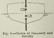
This can best be studied by means of some simple diagrams. The first, figure 9, represents a cross-section of a model boat floating in water in a normal upright position.
The center of gravity is shown at (C.G.), the center of buoyancy at (C.B.); the forces acting through them are in equal and opposite directions. Now, if a horizontal force applied to the vessel causes it to incline to the right and assumes a position shown in figure 10, the center of gravity of the hull will be unchanged, and still remain at the same spot, (C.G.), on the centerline of the boat; but the center of buoyancy will move over to the right. There are three forces acting on the hull, one due to gravity or weight of the vessel acting downwards through the center of gravity, the second force also equal to the weight of the vessel, acting upwards through the center of buoyancy and due to the flotational powers of the vessel. The third force is that which causes and maintains the change of position, and may at present be disregarded.
Two equal, opposite, and parallel forces are termed a couple, and when they act together to maintain a stable condition of the hull they are known as a Righting couple. The moment of the couple is the product of either force into the perpendicular distance between them. Thus the length G-Z (is also known as the stabilizing lever.
By an inspection of figure 10 it will be obvious that the center of buoyancy acting upwards and to the right of the center of gravity, through the agency of G-Z, (the stability lever) exerts a righting force on the hull, causing it to resume the upright position; in other words the vessel is stable.
If the hull were inclined to a much greater angle, as indicated in figure 11, until the center of gravity and the center of buoyancy collide in the same vertical plane, the vessel would remain in this position, the righting moment having reached zero. Should the vessel be heeled still further, the center of buoyancy will travel to the left of the center of gravity, and by augmenting the heeling force will cause the vessel to capsize. Such a couple is known as an upsetting couple.

The word "metacentre" is applied to the point where the vertical line of action through C.B., (when the boat is inclined) crosses the original vertical central plane of the boat.
This point, denominated, "M" is a fixed point for all small angles of inclination, say up to 15° or thereabouts.
The relative positions of C.G. and M determine the stability of the model when M is above G, as in figure 12, the vessel is in a stable condition. When M and G coincide, that is to say, when the metacentric is nil, the vessel is in equilibrium. When M is below G, the vessel will be in unstable equilibrium, and will capsize.
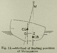
The height of the metacentre depends upon the immersed form of the vessel, and is quite independent of the length of the ship. The height is most conveniently ascertained from a drawing similar to figure 12, showing the vertical line through the center of buoyancy, and extending it to cross the inclined line representing the original vertical central fore and aft plane of the ship. The distance between C.G. and M is known as GM and is equal to the moment of inertia of water plane area about the middle line, divided by the volume of displacement; and is strictly proportional to the square of the breadth, and inversely proportional to the depth.
For all angles of inclination up to about 15° or so the righting lever is equal to the height of GM multiplied by the sine of the angle of inclination from the vertical.
The moment of the restoring couple is equal to:
W x GM sine O,
Where W = displacement;
GM = height of the metacentre above C.G.;
O = angle of inclination.
For moderate angles of inclination the moment of stability is obtained by the above formula. Hence the condition of the sideways rolling of a model boat is governed by the height of the metacentre. (Metacentric heights in real practice are approximately 20 feet for a shallow draft flat-bottomed boat; about 5 feet on a battleship; 3 feet on a light cruiser; about 2 1/2 feet on tugboats; from 6 inches to 2 feet on passenger boats and liners.)
These heights reduced to appropriate scale will be useful as a check on model boat designs. A high metacentre makes a boat stiff or jerky in action, a medium or small metacentric height produces a boat with a low period of oscillation, that is, a boat that has a long, slow roll.
The addition of ballast, or a weight low down in the hull, alters the designed metacentric height and consequently affects the transverse stability. In general it tends to make the boat stiff and roll badly.
The important point to grasp is that stability depends fundamentally upon the distance between the C.B. and C.G. and the distance GM when the boat is inclined; and further, that the action of the boat amongst waves is markedly affected by the metacentric height and by the length of the stability lever. Hence the addition of ballast to correct one fault may introduce others of worse character.
The best design for a given purpose is that which has the most appropriate under-water hull form. When the boat is heeled the shape of that part which is in the water is different, in respect to the water, from what it was when upright. This new form determines the whereabouts of the C.B. in the heeled portion and thus affects the stability and action of the boat.
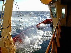
When a model powerboat is traveling through a series of waves, so that, for example, one side of the hull is supported by the crest of a wave and the other side rests in a trough, a heeling force is imparted to the hull, and momentum carries it further in the same direction until all these forces are balanced.
As the boat passes out of the wave the forces diminish and the boat comes back to a normal plane of flotation.
When the wave system is continuous at regular intervals, a rhythmic series of oscillations is set up and the boat continues rolling. The duration and periodicity of such rolling can be determined, or projected, by a rather intricate calculations; the model boat designer is therefore advised to confine attention to the general results obtained from characteristic hull forms and changes in the length of the stability lever.
The longitudinal stability of a vessel is the power it possesses of resting changes of trim, that is, variations of level in four and aft directions.
Actually, the same laws apply as those governing transverse stability, but they are customarily dealt with separately. In one respect the problem is not so pressing because it takes a much greater force to affect the longitudinal stability.
Practically it becomes a matter of correct disposition of the weights in the hull when trimming a model for a maximum longitudinal stability, as their position determines the four and aft position of the center of gravity (C.G.) and this, must in any case be in the same vertical line as the center of buoyancy. But as the position of the center of buoyancy is determined irrevocably by of the shape of the immersed portion of the hull, it follows that the weights in the hull must be moved backwards or forwards until center of gravity is in the vertical plane of the center of buoyancy.
The correct placing of the weights in the model calls for extreme care, as it should be apparent that when the position of the center of gravity altars, the boat must change trim until the immersed portion of the Hull, forwards or aft of the normal center of buoyancy, displaces a sufficient amount of water to restore equilibrium.
This shows the necessity for correct placing of weights, and proper positioning of the foreword and after bodies, as the portions of the hull ahead of, and astern of, the midship section or center of gravity are termed.
To retard pitching, or sinking by the head, a good flare is needed at the bow, and as far as possible, a reserve of buoyancy aft to counteract the evil of squatting, or sinking at the stern.
The proportion of beam to length of hull is known as the beam/length ratio; and this in conjunction with the beam to depth ratio has a marked effect on stability, speed, and the action of the boat amongst waves.
A narrow boat with a fairly deep body is usually unstable; a broad, shallow boat is very stable until considerably heeled.
Various general types of hulls have gradually evolved as the best for specified purposes: broad shallow hulls for racing, new rounded body for an easy sea boat, (with a rectangular section for maximum carrying capacity, and so forth.
The sharpie or box form hull has the maximum initial stability, and a circular section possesses a very low stability in the Sea way, hence to reconcile these differing factors a compromise is often necessary. The foregoing remarks apply particularly to boats of normal form, or those generally called displacement-boats. The conditions governing the actions of hydroplanes or small craft adapted to skim over the surface of the water are in a somewhat different category.
Brief consideration will show that there must be a critical speed beyond which it is important to drive the displacement type boat through the water, because it will clearly take definite time for the water to be pushed aside to allow the hull to pass, and a corresponding time for the water to flow back in again. When a displacement type of boat is driven at higher speeds the hull is forced out of the water at the bow or stern and will ultimately sink.
On Page-1
Note! After you read a paragraph, a click on the paragraph title again, will take you back to top of page.
Hydroplanes
Skin friction
Increased resistance at speed
Eddy Making
Wave making
Bow wave system
Parallel middle body
Stern wave system
The wake
Air resistance
Total resistance
Power needed to drive a model
Transmission losses
Theory of propulsion
The screw propeller
Note! After you read a paragraph, a click on the paragraph title again, will take you back to top of page.
Note! After you read a paragraph, a click on the paragraph title again, will take you back to top of page.
Theoretical Considerations