Theoretical Considerations
From the 1956 book, “Model Power Boats” by Norman G. Taylor
Portland Model Power Boat Assoc., Model Boats and Ships, How does a boat float, Why does a boat float, Buoyancy, Buoyancy theory
Published by Cassell & Co. LTD London
Page -2
Portland Model Power Boat Assoc., Model Boats and Ships, How does a boat float, Why does a boat float, Buoyancy, Buoyancy theory, page-2
Hydroplanes
Hydroplanes
A hydroplane is a boat intended to rise bodily at its critical speed, until it is partly out of the water; this obviously reduces skin friction and therefore allows much higher speeds to be attained. Two separate states or conditions must be considered: first the ordinary laws governing displacement boats, such as the displacement, initial stability and so forth, which must be adequate when the boat is at rest and apply until the critical speed is reached. At and beyond that speed the boat exhibits a new property, which for convenience may be termed dynamic-stability.
An ordinary bicycle exemplifies the phenomena of dynamic stability. The bike, when at rest will not remain unheeded in a vertical position, but when set in motion it acquires the property of stability, and safely and vertically supports the rider. Dynamic stability is imparted to a model hydroplane by reason of the form of the hull and the relative solidarity of the water at high speeds.
On Page-2
RESISTANCE AND PROPULSION
The word resistance is applied in a general sense to the sum of all the forces acting upon a model boat, which retard or entirely prevent its passage through water.
These resistances are due to several separate and distinct causes, and so far as they apply to displacement boats can be subdivided into five groups, which in order of importance are called, skin friction, eddy making, wave making, the wake, and air resistance.
The friction or skin resistance is caused by the friction of the water of the immersed surface of the ship, (or the wetted surface of the hull). The laws governing it have been enunciated by the researches of the late Dr. W. Froude, who found that the resistance varies with the nature and the length of the surface in the direction of its motion; and approximately as the square of the speed.
The experiments enabled the skin friction to be accurately determined, and for all practical purposes the resistance per square foot of wetted surface taken, as a mean over the whole surface of the hull can be fixed at the following values:
A painted hull = .41 lbs.
A waxed painted hull = .38 lbs.
These results were obtained at a speed of 10 fps., which equals 5.92 knots or 6.8 mph.
The approximate resistance of a model powerboat is about .25 lb per sf. of wetted surface at a speed of 6 mph., and in a metre model of average form would be in the neighborhood of .5 lb., assuming a surface of 280 sq in. immersed, at a speed of approximately 7 mph.
It should be noted that the resistance varies considerably according to the nature of the hull surface; hence the practical ship modeler will endeavor to secure a perfectly smooth hull surface.
The foregoing figures for skin friction were taken at a speed of 5.92 knots, but the resistance varies with changes of speed. Skin friction various as the 1.83 power of the speed. The calculations are intricate; consequently the following table of values (Prof Sir H.J. Biles) should be of help to the designer.

The formula for the calculation of fractional resistance do to skin friction is:
RF=FM x M x S
Where:
RF= fractional resistance in pounds.
FM= mean resistance in pounds per square-foot of wetted surface.
M= V the result to the power 1.83
- 92
S= surface of the immersed hull in square feet.
The table is used in the following way:
Suppose, for example, the FM = .41 lb. psf and the model has 2.5 sf. of wetted surface, then FM = 1.025 lbs at 6.8 mph.
To find the resistance at any other speed either in knots or mph., say, for example, 25 mph; under column V equals speed in mph opposite 25.33 read 11.048 as the value of M.
Substituting values in the formula; RF = 1.025 x 11.048= 11.32 lbs.
This enormous increase of resistance with increase of speed is one of the chief reasons why so much more power is needed materially to increase the speed of a given model boat.
(Editor’s note, that’s why your motor (s) get hot if undersized They may function well at slow speed, but when throttle is increased the motors start to fail)
It should also be remembered that skin friction imparts a velocity to the water in the immediate vicinity of the hull and partly causes the zone of fractional disturbance and the fractional wake, and to some extent distorts the stream lines, or energy flow, around the hull.
Eddies are disturbances of the water caused by partial aeration and internal movement of water. Eddy making caused by appendages such as shaft brackets, rudders and sudden changes of the hull form is not a serious energy loss, except that high-speed when it becomes imperative to take all possible steps to eliminate eddies.
The practical remedy is the elimination of all such changes of hull form and a careful streamlining of those, which cannot be dispensed with.
Lord Kelvin defined wave making as an, "orderly progression through matter of a state of motion" and as "the progression of a displacement."
When a model is at rest the hull surfaces are, practically speaking, subject to uniform hydraulic pressure. When the boat is set in forward motion, the distribution of these forces is disturbed, and this change is accompanied by a corresponding alteration or increase of pressure in one part, with a diminution of pressure in others. The surface pressure due to the weight of the atmosphere always remains constant, consequently differences in level become apparent and these differences of level are known as waves.
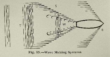
As the boat moves forward, the normal streamlines at the bow are disturbed and a stream of "bow waves" as at be in B fig. 15 is generated.
At the Stern a similar disturbance takes place, the decreasing speed of the streamlines being accompanied by an increase of pressure, and the formation of a stern wave system as at (S.)
The bow wave system is caused by the passage of the body and is a regular wave of translation; the energy needed to generate it is entirely lost.
The middle portion of the boat is usually more or less parallel and causes little or no extra wave making resistance; the only practical resistance of the middle body at ordinary speed is due to skin friction. The increased efficiency of large vessels over properly proportioned smaller models is thus in some measure explained
The conditions around the after body and stern of a model boat when in motion are largely conjectural, but in addition to the diverging stern wave system (S), it is fairly certain that a series of transverse waves as at (T) are generated which appear to follow the ship, together with the wake, as at (W) in fig. 15.
Some of the transverse waves system (T) is due to the fractional disturbance, and some of the energy in it need be returned, as may some of that from they diverging Stern wave system.
Wave making is a necessary evil and cannot be entirely eliminated, although a clever hull designer can do much in this direction.
At low speeds of 1 to 2 mph wave making is practically nonexistent, except with very small boats.
The resistance of the wake is due to the water being set in motion in a forward direction thus resulting in a loss of energy and speed. Some of it may be regained by a suitable propeller arrangement.
Many model boat designers pay very little attention to the loss due to air resistance, although a relatively large portion of a model boat hull is exposed to air currents. Air resistance is only .005 AV (A= area exposed in square feet, V= speed in feet per minute), but it increases as the square of the speed, and at the higher velocities now attained by model boats becomes a factor that should be reckoned with very seriously.
The effect of a head wind is enormous. A model moving at 6 mph in a calm, with an air resistance of only .540 lb., experiences an air resistance of 1.5 lbs. against a head wind of only 4 mph.
The only practical remedy for reducing air resistance is a good aerodynamic design of all cabins, superstructures, and of course good hull design.
The sum of the foregoing resistances constitutes the total resistance to the motion of a boat through water; or more properly to a boat that floats on the water.
One of the greatest problems is to ascertain accurately the volume of the total resistance at the required speed, as without such knowledge it is impractical to determine with precision the power that must be developed at the propeller(s) to overcome drag.
The energy that must be expanded in overcoming the total resistance of a model powerboat at a given speed cannot be calculated with absolute precision; all that can be definitively stated is that the thrust of the propeller(s) must equal the total drag or resistance. That practical difficulty of ascertaining the necessary power of the engine (s) is due in part to difficulties of propeller design.
A very close approximation, however, can be arrived at for boats of normal form and reasonable speed, by application of the following formula.
T= FM x V
33000 Where: T is effective power at the propeller,
FM is total skin friction in lb. At the appropriate speed,
V is speed of the boat in fp min.
Take and as an example the metre boat with 2.5 sf of wetted surface, then FM will equal 1.02 x 6.89 at a speed of 20 mph., equal to 1,773 ft per min.
Substituting values in the formula:
T= 1.02 x 6.89 x 1773 = 12460.28 = .307 hp
33000 33000
This figure is the power required at the propeller, and to ascertain the total power of the power unit an amount must be added to compensate the loss in engine and propeller shaft friction and any other mechanical losses.
This amount may vary from 25% to 70 to 80% according to the efficiency of the plant.
A reasonable average is 40% consequently from the foregoing example of the total power is:
40 x .307 = .122+.307 = .429 hp
100
There are various ways of driving a model powerboat through the water, of which three are commonly used; these are the Jets system, the use of revolving wheels, (or paddle wheels) and by means of a rotating device known as the propeller or water screw.
Marine screw propellers are divided into three groups:
(a)Those, which rotate in the air, such as, swamp buggies.
(b)Those, which rotate partly in the water and partly in the air, such as paddle- wheelers.
(c)The totally submerged water screw or propeller.
The first two groups are not extensively used for model ship propulsion, although in certain circumstance they have sundry practical advantages.
The action of any form of marine propeller, while the boat is in steady motion, is fundamentally dependent upon the sternward projection of a column of water called the propeller race. The change of momentum of this water, per unit time, is equal to the thrust of the propeller, and is balanced by the resistance of the boat.
The basic problem of propeller design is therefore devise an instrument that will force a significant quantity of water in a sternwards direction, and at a sufficient speed, to equal the resistance of the boat at the given speed. So far the submerged propeller has produced the most satisfactory results.
Note! After you read a paragraph, a click on the paragraph title again, will take you back to top of page.


